Taking the wraps off cloaking
Introduction
We have a touching faith in the ability of our eyes to tell the truth. No other sense has such confidence invested in it, so when our eyes deceive us the result is bewilderment, giving rise to appeals to magic or even the supernatural. This explains the enormous interest aroused by recent work on invisibility and the cloaking of objects from electromagnetic radiation. In this article we review the theories and experiments behind the hype and suggest what devices might realistically be expected in the near future and what is likely to prove impossible.
Hard wired into our brains is the expectation that light travels in straight lines. Mostly this is true, but there are well-known exceptions, such as mirages, which occur when a hot surface heats the air above, reducing its density and hence creating a refractive index gradient immediately above the surface (Fig. 1, top). Such a gradient bends the trajectories of light rays so that an observer misinterprets where the light is coming from. Typically, light from the sky is refracted by the gradient, giving the appearance of water shimmering in the distance—hence a cruel illusion seen by a thirsty traveler in the desert or, more prosaically, the appearance of a wet road on a hot day.
It is the ability of refractive index gradients to bend light that the invisibility engineer exploits. Light is steered around the hidden object by a cloaking device, and then returned to the same straight line trajectory, rather as a skier would make a chicane around a tree (Fig. 1, bottom). The observer’s brain is unaware of the possibility of chicanes and sees only that which is behind the cloak and nothing of the cloak itself or of its contents. The real challenge of cloaking lies in deriving a theoretical prescription for the optical properties of the cloak and, even more challenging, realizing these properties in a material. Transformation optics provides the theoretical background and metamaterials provide the means of achieving the prescribed parameters.
Transformation optics
It was Michael Faraday who stressed the importance of “lines of force.” He could see magnetic lines of force aligning iron filings placed near his magnets, and for him they represented physical reality. Lines of force are continuous and their density represents the strength of a field. Likewise, electric field lines are also continuous, at least in the absence of electrical charges. In fact, any conserved vector quantity can be represented in this way, and one can add the Poynting vector, representing the flow of electromagnetic energy, to this set. The Poynting vector is merely the mathematical representation of a “ray” of light.
Maxwell’s equations are a mathematical realization of Faraday’s work. They describe the phenomena of classical optics and it has long been known that their form is invariant under coordinate transformations. For example, if the equations are written using a Cartesian system,
where μ(r) and ε(r) are the magnetic permeability and electrical permittivity tensors, respectively, then rewriting the equations using a cylindrical coordinate system changes only the values taken by μ and ε. Andrew Ward and I used this result to adapt computer codes written specifically in a Cartesian system to make computations for optical fibers, which require cylindrical symmetry [1]. This invariance of form is true under any coordinate transformation and can be exploited to generate a whole family of optical devices from a single canonical device. Further references can be found in Ref. [2].
Following in the footsteps of Faraday, we can give physical meaning to a coordinate transformation as follows: imagine starting from a Cartesian system with a given set of electric and magnetic fields, and their associated Poynting vectors. Next, imagine that the coordinates are continuously distorted into a new system. Transformation optics was born of the realization that lines of force are effectively glued to the coordinate system [2]. As the system is distorted it carries with it all the associated fields. Hence to guide the trajectory of a ray of light, only a distortion in the underlying coordinate system is needed, automatically taking with it the light ray. Knowledge of the transformation in turn provides the values of μ and ε required to steer the light in this way.
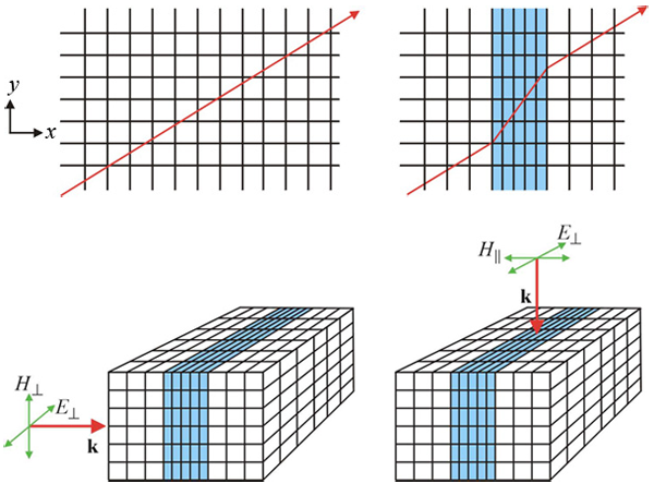
To give a flavor of how the scheme operates, imagine the simplest possible distortion of space: a section of the x axis is compressed as shown in Fig. 2. Now probe the compressed region with two rays in order to find the values of ε(r) and μ(r) that would give rise to the ray trajectory shown, and note the following: ε(r), μ(r) are tensors because the x axis is singled out for compression; in the uncompressed regions there is no change, so ε(r)=μ(r)=1 in these regions; ε(r) and μ(r) appear on the same footing because of the symmetry between electric and magnetic fields. It follows from the last assertion that ε(r)=μ(r) .
Next consider a ray propagating parallel to the x axis. In order to arrive at the far side of the compressed region with the same phase as in the uncompressed system, the condition k′md=k0d must hold, where k0 is the free-space wave vector, k′ is the wave vector in the compressed region, m is the compression factor, and d is the original thickness of the layer. Since k′=k0√εyμy, where εy and μy are the components of the respective tensors perpendicular to the x axis, then it follows that
On the other hand, rays propagating perpendicular to the x axis travel through uncompressed space, and therefore their wave vector, k′′, must take the free-space value if the correct phase evolution is to be followed. In this case,
and therefore we have
In addition, because ε(r)=μ(r), the compressed layer is impedance matched and does not reflect.
The effect of distorting a coordinate system can be expressed very simply: along a direction of compression both ε and μ are decreased by the compression factor; in the perpendicular directions ε and μ are increased by the inverse of the compression factor. For a general compression, the formula is applied successively along each of the three axes.
The above gives an intuitive version of our scheme. A more formal derivation was presented by Ward and Pendry [1] and an updated version by Schurig et al. [3], using modern notation [4]. We follow the latter version here. If the distorted system is described by a coordinate transform x′j′(xj), then defining
so that in the new coordinate system we must use modified values of the permittivity and permeability to ensure that Maxwell’s equations are satisfied:
The theory is exact as far as Maxwell’s equations are concerned and applies as much to steering magnetic and electric fields as it does to steering rays of light. Further details of the theory can be found in Refs. [5,6].
Invisibility
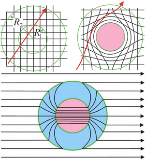
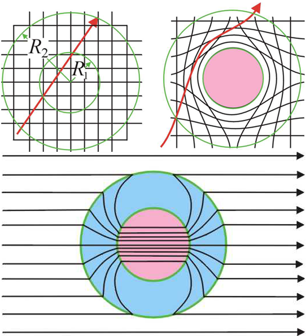
Figure 3 (top left) shows a ray of light travelling in free space. We wish to hide the contents of a sphere radius R1 by directing the rays around this region, but requiring that any distortion of trajectories is confined within a larger sphere radius R2 (Fig. 3, top right). In this way an external observer would be aware neither of the presence of the cloak nor its contents. The illusion of empty space has been created.
Exactly how to compress the coordinates into the cloaking region is a matter of choice. Here is a simple transformation that does the job:
giving rise to the cloaking parameters
Note that the compression axis lies along the radius and along the perpendicular directions, i.e., along the angular coordinates the values of ε and μ are increased by the inverse of the compression factor, whereas along the radial direction the values are reduced. This prescription is an exact solution to the cloaking problem at the level of Maxwell’s equations [7]. Both the near field and the far field are cloaked and the theory can even be applied to dc fields [8]. An alternative cloaking scheme was published simultaneously [9], exact to the level of the ray approximation. Ray schemes demand only the manipulation of the refractive index and therefore have advantages in simplicity of construction. Much earlier work [10] discussed the cloaking of objects to electrical currents flowing in a medium.
A simplified version of this cloak was demonstrated for microwaves in 2006 [11] using the concept of metamaterials. These new materials owe their properties as much to their subwavelength internal structure as to the materials from which they are manufactured. We shall examine their properties in greater detail later on.
There followed a huge surge of interest both from scientists and engineers implementing their own versions of the technology, and from the popular press where it has inspired many articles on the subject, raising the profile of electromagnetic phenomena to levels not previously seen. The first cloaking papers based on transformation optics appeared in 2006 and have already been cited more that 500 times.
There is more than one route to cloaking. An alternative approach, shown in Fig. 3, (bottom panel) is to recognize the properties of the cloaked object and construct the cloak to cancel any scattering so that the cloak and object together are invisible. [12,13]. Some remarkable effects have been shown to be possible with such schemes, at least on theoretical grounds. For example, a recent paper [14] proposes a way to hide an object without having to wrap the cloak around it, and it is even possible to replace a given object with another [15], thus increasing the possibilities for deception even further! These cancellation schemes always involve materials with either ε<0,μ<0, or with both quantities negative. Negative values imply in turn that there is a strong frequency dependence and such cloaks work at highly specific frequencies, deriving their properties from resonances within the cloak.
One interpretation of a cloak is that it makes the cloaked object appear to be extremely small and therefore invisible, so that the spherical cloak shown at top right in Fig. 3 would shrink the object to a sphere of vanishing radius. Although the sphere would have an extremely large refractive index, it would still be invisible in the limit. This picture immediately suggests two other possibilities: shrinking the object to a cylinder of vanishing radius or down to the plane of vanishing thickness. A very thin cylinder is invisible, even if conducting, because a thin wire is highly inductive and therefore can carry no current, so the cylindrical scheme is a possible route to perfect invisibility and in fact has been the model most commonly implemented. The third possibility of reducing the object to a plane does not produce an invisible object since a highly refracting plane of material reflects incident light. However, if the environment of the cloak already contains a reflecting surface, the squashed object is effectively hidden if it appears to lie on this existing reflecting surface. Hence the term “carpet cloak.” This latter cloak, although far less general in application than the other two, is easy to build because the material parameters required are no longer singular, as is the case for the sphere and the cylinder.
Although theory gives a perfect prescription for a cloak, implementation is a different matter. The metamaterials employed are in general anisotropic and the difficulty of manufacturing them increases severely at higher frequencies. A spherical cloak is singular on its surface, i.e., the values of ε and μ either →∞ or →0, and therefore any practical implementation will always involve a degree of approximation.
Metamaterials: are they up to the task?
Many wonderful schemes for cloaking have been dreamt of, but if in the last analysis the materials needed for their manufacture cannot be found, they remain theoretical dreams. Fortunately, some of the cloaking proposals are relatively easy to implement and the range of materials available to us has been hugely extended by the concept of a metamaterial.
The idea behind metamaterials is that electromagnetic properties can be altered by changing the physical structure of an existing material. A simple example would be to create a series of voids in a dielectric. If the voids are much smaller than the relevant wavelength, incident light will see only an average response and a reduced effective permittivity. More complex structures, such as tiny metallic resonators, can produce more exotic effects, including negative refractive indices. Provided that the structure remains much smaller than the wavelength, properties can be interpreted in terms of an effective ε and μ. As it happens, nature has not been generous with the electromagnetic properties of materials: only a limited range is on offer and some properties, such as a negative refraction, are entirely absent in naturally occurring materials. In fact, it was the ability of metamaterials to produce negative refractive indices that first drove them to prominence. Since that time, the concept of function through structure has been deployed to implement many theoretical schemes previously thought to be beyond reach. Cloaking demands, in particular, materials whose properties are continuously graded throughout the cloak and are in general anisotropic. Metamaterials are ideally adapted to these demands.
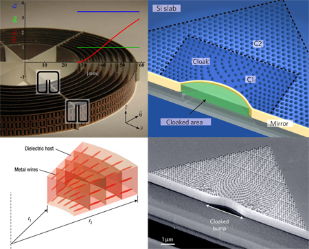
The first implementation of a cloak by researchers at Duke University employed resonant metallic elements of the “split ring” [16,11] design, illustrated in Fig. 4 (top left). This was convenient because the structure can readily be tuned to give a wide range of responses, but carries the penalty that the response depends strongly on frequency and hence this cloak operates only on the design frequency. Also, approximations were made. An ideal cloak requires ε and μ to be equal at every point. This ensures that not only is the refractive index graded so as to steer rays of light around the hidden object, but also the material is impedance matched to vacuum, eliminating any spurious reflections at the interface. If impedance matching is neglected, and reflections are minimized by smoothly grading the cloak at the vacuum interface, then the refractive index variations can be entirely accommodated by adjusting either ε or μ
This approximation is particularly useful at higher frequencies, where magnetic metamaterials are hard to engineer, and has also been exploited [17] to propose an optical version of the cloak. The bottom left panel of Fig. 4 shows a design incorporating metallic wires in a dielectric host to create a radial gradient of the permittivity. Simulations show that the design should be effective in cloaking illumination with transverse-magnetic polarization.
Subsequent designs have been produced incorporating nonresonant elements and have a wide band of operating frequencies. The so-called “carpet cloak” described above is particularly well suited to nonresonant designs because it does not demand extreme values of the parameters. It has recently been implemented at microwave frequencies by the Duke team and shown to operate over a broad band.
An exciting development in the past year has been cloaking at near ir frequencies. The “carpet cloak” template has been used by two groups, one in Berkeley and the other in Cornell, to create a cloak using silicon and silica in a 2D waveguide [18–20]. Figure 4 (right panels) shows the device manufactured by the Berkeley group. To produce a cloak, the density of silicon, and therefore the refractive index, is varied by drilling holes. Experiments on the structure show that light incident from any angle reflects from the cloaked bump as though from a flat reflecting surface. Cloaking is effective over a broad band of frequencies.
Another inventive approach to the problem of optical cloaking, from the Purdue group [21], employs a 2D waveguide of varying height. This has the effect of varying the cutoff frequency and hence the effective refractive index for light propagating in the guide. By tuning the height variation to that demanded by cloaking theory, light can be forced to avoid a given region of the 2D guide, emerging from the cloaking region as if the guide were of uniform cross section. Any object could then be hidden in the avoided region.
Beyond electromagnetism
The mainstream work on cloaking has been inspired by the beautiful symmetry of Maxwell’s equations under coordinate transformation, but the successes in realizing an electromagnetic cloak have prompted many to ask whether the methods of transformation optics can be applied to other systems to generate cloaks for sound waves, water waves, or even for earthquakes [22]. Work on acoustics is the most fully formed.
Initial investigation of sound propagation in elastic media [23] showed that, in general, coordinate transformations do not have such elegant consequences as for Maxwell’s equations: the form of the equations changes and new terms appear corresponding to unphysical forces. But restricting our attention to fluids where only longitudinal modes are present removes these difficulties [24], and Chen and Chan [25] report that for a fluid, a coordinate transformation can be represented as a change of density, which becomes a tensor, and a modulus, which remains a scalar. This has led to several papers reporting designs for acoustic cloaking.
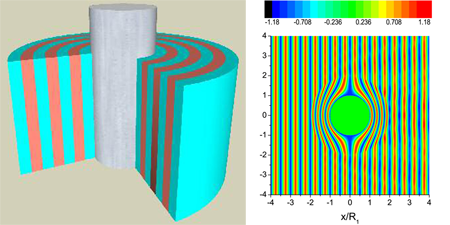
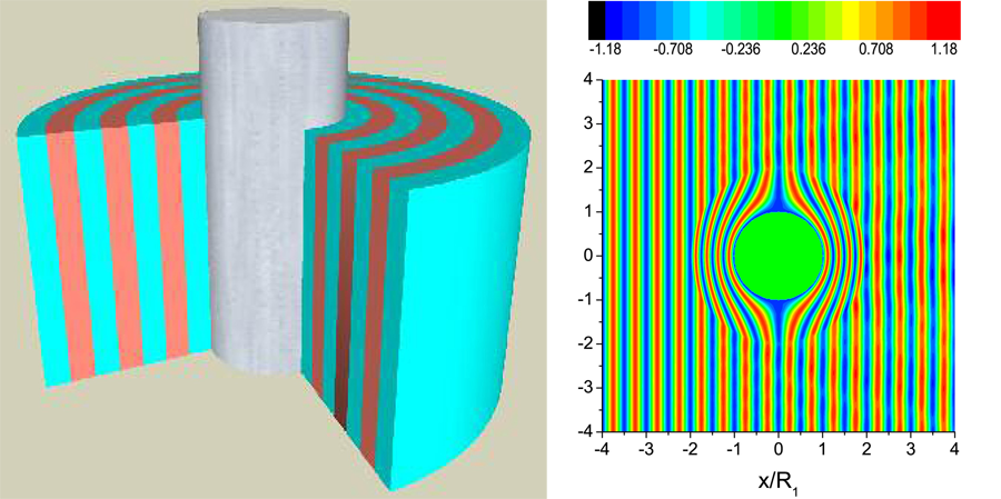
Daniel Torrent and José Sánchez-Dehesa [26] have proposed an ingenious way to realize these theoretical schemes. The problem lies in producing anisotropic acoustic materials. This problem is addressed by considering a structure comprising layers of isotropic materials, the anisotropy following from the layering. Figure 5 illustrates the scheme, which was tested in a computer simulation. Clearly, the device is operating extremely efficiently. Torrent and Sánchez-Dehesa had specifically in mind that their cloak should be feasible to construct. Although, as yet, an actual device has not appeared, given the interest in acoustic cloaking from many quarters, it cannot be long before a practical implementation follows.
Summary
Design and construction of a cloak is in the nature of a grand challenge for optics. On the theoretical side, transformation optics provides a complete prescription for a cloak, but practical implementation requires mastery of metamaterial construction. At rf frequencies, progress has been impressive, with several demonstrations of a cloak, and most recently, optical cloaks have been constructed, albeit of restricted capability. In the future we can expect further progress at all frequencies, with practical applications emerging first at rf. However, it has to be said that for the foreseeable future, cloaks will be substantial rigid devices, and in that respect, “cloak,” with its implication of flexibility, is a misnomer.
The challenge has also extended to acoustic systems where there is a host of applications awaiting viable cloaking technology. Although applications are, for the moment, limited to fluids such as water or air, this is where some of the most important applications are to be found.
Finally, as with many grand challenges, it will probably be the case that the technology being developed will have many more applications than cloaking. The ability to design and build a system that exerts detailed control over the flow of radiation is a powerful tool that is bound to find many applications, though perhaps not all of quite such a sensational nature as a cloak.
References
- A. J. Ward and J. B. Pendry, J. Mod. Opt. 43, 773 (1996)
- J. B. Pendry, Contemp. Phys. 45, 191 (2004)
- D. Schurig, J. B. Pendry, and D. R. Smith, Opt. Express 14, 9794 (2006)
- D.M. Shyroki, http://arxiv.org/abs/physics/0307029v1
- U. Leonhardt and T. G. Philbin, New J. Phys. 8, 247 (2006)
- J. B. Pendry in Coherence and Quantum Optics IX, edited by N. P. Bigelow, J. H. Eberly, and C. R. Stroud, Jr. (OSA Publications, 2009), p. 42
- J. B. Pendry, D. Schurig, and D. R. Smith, Science 312, 1780 (2006)
- B. Wood and J. B. Pendry, J. Phys. Condens. Matter 19, 076208 (2007)
- U. Leonhardt, Science 312, 1777 (2006)
- A. Greenleaf et al., Math. Res. Lett. 10, 685 (2003)
- D. Schurig, J. J. Mock, B. J. Justice, S. A. Cummer, J. B. Pendry, A. F. Starr, and D. R. Smith, Science 314, 977 (2006)
- A. Alu and N. Engheta, Phys. Rev. E 72, 016623 (2005)
- G. W. Milton, and N. A. Nicorovici, Proc. R. Soc. London A, 462, 3027 (2006)
- Y. Lai et al., Phys. Rev. Lett. 102, 253901 (2009)
- Y. Lai et al., Phys. Rev. Lett. 102, 253902 (2009)
- J. B. Pendry, A. J. Holden, D. J. Robbins, and W. J. Stewart, IEEE Trans. Microwave Theory Tech. 47, 2075 (1999)
- W. Cai, U. K. Chettiar, A. V. Kildishev, and V. M. Shalaev, Nature Photon. 1, 224 (2007)
- Jensen Li and J. B. Pendry, Phys. Rev. Lett. 101, 203901 (2008)
- Jason Valentine, Jensen Li, Thomas Zentgraf, Guy Bartal, and Xiang Zhang, Nature Mater. 8, 568 (2009)
- Lucas H. Gabrielli, Jaime Cardenas, Carl B. Poitras, and Michal Lipson, Nature Photon. 3, 461 (2009)
- I. I. Smolyaninov, V. N. Smolyaninova, A. V. Kildishev, and V. M. Shalaev, Phys. Rev. Lett. 102, 213901 (2009)
- M. Farhat, S. Guenneau, and S. Enoch, Phys. Rev. Lett. 103, 024301 (2009)
- G. W. Milton, M. Briane, and J. R.Willis, New J. Phys. 9, 248 (2006)
- S. A. Cummer and D. Schurig, New J. Phys. 9, 45 (2007)
- H. Chen and C. T. Chan, Appl. Phys. Lett. 91, 183518 (2007)
- D. Torrent and José Sánchez-Dehesa, New J. Phys. 10, 023004 (2008)

