All-optical compass based on the effect of electromagnetically induced transparency
Magnetometers are among the most widely used physical devices, finding applications in medicine, geology, cosmology, fundamental physics, and other areas (see Refs. [1,2] for review articles). For instance, vector magnetometers were employed recently to guide the drilling of relief wells to handle the oil spill in the Gulf of Mexico [3]. In spite of the impressive history of ultrasensitive magnetometry, the field is still active and significant efforts are underway to enhance accuracy of existing devices and to create novel ones possessing superior features. As an example of this progress, Valeriy Yudin and colleagues at the Institute for Laser Physics in Novosibirsk, Russia, now report in Physical Review A [4] a way to employ the interaction of light with an atomic vapor to achieve senstive all-optical vector magnetometry.
Magnetometers can measure the flux (for example, with superconducting quantum interference devices, or SQUIDs) or the amplitude of a magnetic field. The magnetometers that are sensitive to the amplitude of the field can be scalar or vector. Scalar magnetometers are insensitive to the direction of the magnetic field, while the vector magnetometers detect not only the absolute value of the field, but also its direction. The conventional way of making a vector magnetometer is to use a scalar magnetometer and measure the linear combination of the magnetic field under study, as well as several reference magnetic fields having known direction and magnitude. Some optical magnetometers are sensitive to only specific cartesian components of the magnetic field and can be used as vector magnetometers [2].
Magnetometry with atomic systems is promising because it allows both high-sensitivity and high-accuracy magnetic field measurements. The atoms play the role of quantum transducers converting information about the magnetic field into measurable values. In this case, the magnetic field shifts the atomic energy levels and introduces an observable Larmor spin precession. Since the number of atomic species conveniently suitable for magnetometry is limited (usually alkali atoms and helium are used), the recent progress in the field is generally related to development of the most sensitive readouts, e.g., RF field and light, for the atomic observables.
One of the most promising directions in this area is all-optical magnetometry, since it allows fabrication of chip scale devices [2,5,6]. Only light is used to interrogate the atoms influenced by the magnetic field. The problem is how to achieve the highest sensitivity and accuracy of the measurements and how to obtain the information about both the amplitude and direction of the magnetic field from the measurement. The work of Yudin et al., based on electromagnetically induced transparency in linearly polarized light [4], proposes a solution for the problem.
Electromagnetically induced transparency (EIT) [7] and coherent population trapping (CPT) [8] are processes that represent the core of the optical compass discussed in the paper. Optical fields produce “dark” states in the atomic medium, leading to formation of narrow transparency resonances for the light. The dependence of the frequency and the contrast of those resonances on the polarization of the light, together with the direction and the magnitude of the magnetic field is used in the magnetometer. EIT is a two-photon process and to interrogate the atoms, Yudin et al. use linearly polarized bichromatic light. The frequency components of the light have the same polarization direction. This results in high-contrast EIT resonances that appear when the light interacts with line of and the frequency difference of the optical frequency components coincides with the hyperfine frequency splitting of the ground state of the atoms modified by the magnetic field under study (see Fig. 1 of Ref. [4]). The large contrast value is important as it contributes to the signal-to-noise ratio of the measurement and to the sensitivity of the magnetic field detection.
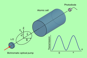
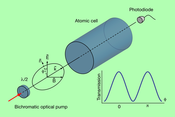
In their paper, Yudin et al. note that the attenuation of the bichromatic linearly polarized light in vapor depends on the relative directionality of the optical wave vector , the optical polarization , and the direction of the magnetic field under study, . The medium becomes the maximally transparent when the magnetic field and the optical polarization are mutually orthogonal: (Fig. 1). The effect has the maximum magnitude when the frequency separation between the optical frequency components is equal to the frequency of the clock transition, (i.e., the transition between magnetic sublevels of the hyperfine states used in atomic clocks).
The measurement procedure is rather simple. One selects vector and measures the attenuation of the light as a function of the rotation angle of the polarization , around . In the experiment, the polarization rotation is achieved by mechanical rotation of a plate (a device that rotates the linear polarization), as shown in Fig. 1. The maximum transparency is achieved when , which determines the plane ( ) formed by vectors and . One finds another plane ( ) by changing the propagation direction from to and repeating the measurement. The intersection line of the two planes gives the orientation of with an uncertainty of the sign.
The accuracy of the measurement is limited by the accuracy of the determination of planes ( ), and hence by the accuracy of settings of and . In the experiment reported in the paper the direction of the light propagation is determined pretty well, while the directionality of the polarization, given by a mechanical setup involving a rotating wave plate, is not very accurate. The accuracy can be improved if one monitors the polarization direction independently using, e.g., a high-quality polarizer with accurately preset direction (the light sent through the polarizer should not pass the atomic cell).
The sensitivity of the measurement to small variations of magnetic field is determined by the optical shot noise. It can be as small as degrees/ for a large magnetic field when the degeneracy between the Zeeman sublevels is removed. The sensitivity of the magnetometer is limited by the white noise so the sensitivity increases when one reduces the frequency bandwidth of the measurement (which increases the time over which the measurement is performed). The overall dynamic range of the magnetometer is approximately – , which is particularly suitable for applications in geology and cosmology. It is worth noting that the sensitivity to the small magnetic field can be improved if one adds a bias dc magnetic field in a given direction. The measured sensitivity of the device to the direction of the magnetic field can be lower than the sensitivity of existing vector magnetometers. For example, if a scalar magnetometer has readily achievable sensitivity [1,2], the direction of field vector can be determined with sensitivity of a microdegree per with help of this magnetometer. However, the practically achievable sensitivity is determined by the accuracy of the direction as well as the magnitude of the bias magnetic fields, necessary to transform the scalar device into vector one, which is significantly less than a and microdegree, respectively. The all-optical compass does not need a bias magnetic field and its sensitivity is limited by the optical pump-associated noise only.
The proposed method is suitable for the measurement of both the absolute value and the direction of the magnetic field. To measure the absolute value of the field one needs to measure the frequency difference between the EIT resonances produced by the so-called systems formed at the ground state sublevels . The authors found that such a frequency-differential magnetometer is immune to collisional shift resulting from the interaction of the rubidium vapor with the buffer gas, as well as rubidium atom-atom interactions; such a system is also insensitive to the ac-Stark and quadratic Zeeman shifts. The scalar magnetometer does not have “dead” zones as it operates at the arbitrary mutual orientation of the vectors and .
Several other methods of vector magnetometry using the phenomena of EIT and CPT have been proposed previously. Those techniques utilize the magnetic field dependence of the absorption [9] and refraction [10] of the coherent atomic medium in the vicinity of the dark resonances. It was shown that nonlinear magneto-optical polarization rotation [11] can also be used for vector magnetometry since it is strongly affected by the magnitude and direction of transverse magnetic fields. However, a large amount of mathematical modeling is required in those schemes to reconstruct the vector of the magnetic field from experimental data.
Yudin et al. pointed out that the transmission of the atomic cell interrogated with the bichromatic linearly polarized light is not sensitive to the sign of and because of symmetry reasons. The symmetry (see Eq. and Eq. of Ref. [4]) directly suggests the universal extrema of the angular transmission dependence for arbitrary values of the parameters and processes, such as light intensities, one-photon detunings, the intensity profile of the light beam, the atomic density, the diffusion motion of the rubidium atoms in the buffer gas that is placed in the atomic cell along with rubidium atoms, the atomic collision-related processes (depolarization, broadening, shifts), and so on. Thus the proposed 3D compass, unlike its predecessors, does not require subtle mathematical modeling.
To conclude, the idea reported by Yudin et al. [4] looks simply and practically feasible. The authors found an optimal frame of reference and optimal properties of the optical probe that simplifies retrieval of the information about the magnetic field from the atomic medium. This might allow an atomic clock and magnetometer to be made in a single package using the same atomic cell. A significant effort, though, will be required to develop this idea into an operational device and future work needs to include extensive modeling of such devices not covered in the present work.
References
- E. B. Alexandrov, M. V. Balabas, A. S. Pasgalev, A. K. Vershovskii, and N. N. Yakobson, Laser. Phys. 6, 244 (1996)
- D. Budker, and M. V. Romalis, Nature Phys. 3, 227 (2007)
- D. Schneider, IEEE Spectrum Magazine 42, 11 (2010)
- V. I. Yudin, A. V. Taichenachev, Y. O. Dudin, V. L. Velichansky, A. S. Zibrov, and S. A. Zibrov, Phys. Rev. A 82, 033807 (2010)
- A. B. Matsko, D. Strekalov, and L. Maleki, Opt. Commun. 247, 141 (2005)
- V. Shah, S. Knappe, P. D. D. Schwindt, and J. Kitching, Nature Phys. 3, 227 (2007)
- M. Fleischhauer, A. Imamoglu, and J. P. Marangos, Rev. Mod. Phys. 77, 633 (2005)
- E. Arimondo, Prog. Opt. 35, 257 (1996)
- R. Wynands, A. Nagel, S. Brandt, D. Meschede, and A. Weis, Phys. Rev. A 58, 196 (1998)
- H. Lee, M. Fleischhauer, and M. O. Scully, Phys. Rev. A 58, 2587 (1998)
- D. Budker, W. Gawlik, D. F. Kimball, S. M. Rochester, V. V. Yashchuk, and A. Weis, Rev. Mod. Phys. 74, 115 (2002)


